Textures
We have seen how to tint meshes using colors directly on the vertices, but this does not give us a level of detail at the pixel level. We cannot create one vertex per pixel, however, we can load an image onto the GPU and use it as a texture that covers the mesh surface.
Mapping a rectangular image to a rectangular mesh is trivial, but the complexity increases quickly for other shapes. We will specify how to map textures using a vertex attribute called texture coordinate.
- Texture coordinates are set using the five parameter version of
vertex(). - The first three parameters are the position
xyzand the last two are the texture coordinatesuv. ugoes in the horizontal direction andvgoes in the vertical direction.- Note that we always need to include the
zcoordinate in this version. We can just set it to0.0if we are working in 2D.
The texture coordinate attribute is added by p5.js in the aTexCoord variable of the vertex shader. If we pass it to the fragment shader using a varying and render out its value, it should display a smooth gradient. This happens because texture coordinates are usually normalized, ranging from 0.0 to 1.0. When we set the red channel of the fragment to u and the green channel to v, we can see the red value gradually increasing as we move right and the green value gradually increasing as we move down.
To use these coordinates with an image, we need to load the image in our sketch and pass it to the shader as a uniform variable. Images and other textures are represented by the type sampler2D. A texture is just an array of numbers in GLSL, and in this case a two-dimensional array (width and height), hence the 2D in sampler2D.
Textures are sampled using the texture2D() function, which takes the texture as a first parameter, and a texture coordinate as the second parameter.
Try scaling the coordinate before sampling the texture to understand how it works. If we scale the image down, we will see a streak of pixels coming off the right and bottom of the image. These streaks are the last row and column of pixels repeated, and is the default sampling behaviour when using texture coordinates that are out of bounds.
If we happen to be using a texture with width and height both powers of 2 (i.e. 128, 256, 512, 1024, …), we can change the texture wrap mode with the textureWrap() function.
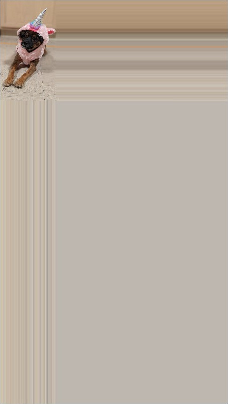
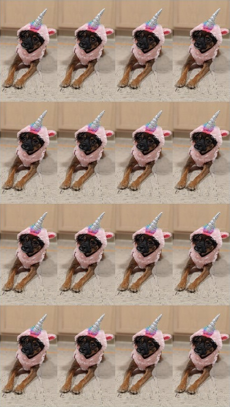
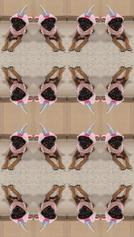
Image Processing
Once our texture color is sampled, we can further process it before writing its value to gl_FragColor.
The following example converts the color to grayscale. Note that the vec4 components can be accessed using either xyzw or rgba.
We have a few options for conversion. In all cases, we need to convert the image from the 3 RGB channels into a single channel value.
- We could use the max value, called the brightness.
float grayVal = max(texColor.r, max(texColor.g, texColor.b));
- We could use the average value, called the lightness.
float grayVal = (texColor.r + texColor.g + texColor.b) / 3.0;
- We could calculate a weighted average, called the luminance. The following formula takes into account human eye perception, which is more sensitive to green.
float grayVal = texColor.r * 0.21 + texColor.g * 0.71 + texColor.b * 0.07;
The grayscale value can be thresholded easily using an if statement. In the example below, the threshold value is set dynamically as a uniform using the mouse.
As we did with the color attribute examples, we can pass in a uniform for time and use it to animate an effect. The following example does RGB displacement by sampling different pixels for each of the red, green, and blue channels.
This effect works best when we use neighboring pixels so we need to calculate what the offset corresponding to 1 pixel is for a texture coordinate. We can do this easily by dividing the texture coordinate range 1.0 by the image dimensions image.width and image.height.
We can blur the image using a similar technique. A quick and easy way to blur a pixel is to set its value using an average of its neighbors. The following example does this using the four direct neighbors (up, down, left, right).
Exercise
Create a blurring effect shader that uses a 9x9 kernel around the pixel. This means that each pixel should sample values with offsets [-4, -3, -2, -1, 0, 1, 2, 3, 4] in each dimension, then average the result.
- Use
p5.Captureas a live image. - Build two versions of this, one using shaders and one using only CPU code.
- The GPU version should use a loop in the fragment shader.
- The CPU version should use the
pixelsarray inp5.Captureto access the data.
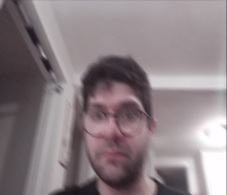
Notice how much more complex the code is in the CPU version, and how much slower it is running compared to the shader version!