We have been focusing on WebGL for most of the course but this is just a small part of the world of shaders.
As shaders are the language for programming graphics, most tools and frameworks have some type of interface for working with the GPU. Different OpenGL versions and platforms each have their own unique GLSL commands, and other systems like DirectX use a completely different language. However, the concepts under the hood are all very similar, so it is just a matter of getting familiar with the syntax to leverage the power of the GPU.
Let’s explore a few different platforms and explore this first hand.
Processing
Processing is the precursor to p5.js and therefore uses a lot of similar syntax. Processing is written in Java and predominantly runs on Desktop and Android. Similarly to how p5.js needs a WEBGL canvas to run WebGL code, Processing needs a P2D or P3D renderer to run OpenGL code.
|
|
Shaders are loaded inside a PShader object using loadShader(). The shader is enabled using the shader() function, and everything drawn after the call will use the enabled shader program.
|
|
By default, shaders in Processing use OpenGL 2.0. This is pretty much equivalent to WebGL 2, which is what we have been using in p5.js and three.js. The built-in uniforms and attributes use a different naming convention, without any prefixes like u or a so that’s something to pay attention to. The position attribute also already comes in as a vec4 so we can use it directly in our MVP transformation.
|
|
Processing also passes the entire MVP as the transform uniform, which can be used in a simple matrix multiplication to calculate our clip position.
|
|
Download the project here.
For more information, the Processing Shaders Tutorial is a good starting point. (This tutorial went offline at the time of this writing, but can still be accessed through the wayback machine.)
openFrameworks
openFrameworks (OF) is an open source cross-platform creative toolkit. Like p5.js, is also originally based on Processing, but has taken its own shape as it has developed over the years. OF is written in C++, which is a lower level language than Java or Javascript. This has the advantage of giving the programmer much more control, but can also be more complicated as there are more ways to break things and more things to manage. For more information, you can read through the Intro to openFrameworks page on the Seeing Machines course site.
openFrameworks also uses OpenGL for rendering. Programmers have the option to set the OpenGL version to use for each application. Many OF users prefer to use the programmable pipeline (OpenGL 3.0 and up) as it allows more control when rendering meshes and graphics. This can be set in the main() function, which is the entry point into the program.
|
|
openFrameworks uses ofMesh to generate and render geometry, and ofShader to compile and bind shader programs. For more information, the ofBook Introducing Shaders section is a good introduction.
OpenGL 3.x+ shaders need their version defined at the top using a #version ### command. This tells the shader compiler which features we are planning on using, and these can be cross-checked with the version of the API we are using on the CPU side of the app. When looking up variables and functions in the GLSL reference, compatible versions are listed at the bottom of the page.
The OpenGL and GLSL version numbers don’t match up until version 3.30, so you will need to use a table like the following to find corresponding values.
| OpenGL Version | GLSL Version |
|---|---|
| 2.0 | 1.10 |
| 2.1 | 1.20 |
| 3.0 | 1.30 |
| 3.1 | 1.40 |
| 3.2 | 1.50 |
| 3.3 | 3.30 |
| 4.0 | 4.00 |
| 4.1 | 4.10 |
| 4.2 | 4.20 |
| 4.3 | 4.30 |
| 4.4 | 4.40 |
| 4.5 | 4.50 |
To keep things simple, I would suggest sticking with #version 330 for OpenGL 3.3 as that will be compatible on most Desktop platforms.
Programmable pipeline shaders do not use the attribute and varying qualifiers. Instead, they use in to represent values that are input into the shader unit, and out for values that are output out of the shader unit.
In the vertex shader:
- attributes use the
inqualifier. - varyings use the
outqualifier.
|
|
In the fragment shader:
- varyings use the
inqualifier. Their name must still match theoutof the vertex shader. - there is no
gl_FragColorvariable. Anout vec4variable must be declared to set the output color. This variable can be named whatever you want.
|
|
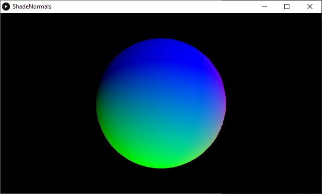
Download the “Normals” project here.
Transform Feedback
Meshes are an abstraction of something called a vertex buffer object or VBO. A VBO is simply a data structure that stores vertex information. Up until now, we have filled VBOs on the CPU, then uploaded them to the GPU for shader processing and rendering.
OpenGL for desktop includes the transform feedback extension, which allows us to write to VBOs in our vertex shaders. These VBOs can be used as geometry input to different parts of the program, and can even be mapped back to a CPU data structure, meaning we can recover computations made on the GPU! This concept is similar to how we have been using offscreen render buffers and textures for multi-pass image effects, except in this case we are manipulating and retrieving meshes directly.
When setting up an ofShader, we can use ofShader::TransformFeedbacksettings to tell it which varyings we want to capture in our buffer. In this case, we will capture the position and color, both calculated in the vertex shader. Note that the shader only requires a vertex unit, as we are not drawing anything to the screen and do not need a fragment shader.
|
|
We then bind the buffer as we enable the shader, so that whatever geometry we output gets saved into the buffer.
|
|
The VBO can then be used like a mesh or any other geometry data. In OF, we can bind the data to an ofVbo to render it in another pass. The feedback data will be interleaved, meaning all the position and color data will be packed into the same array, one vertex after the other: XYZWRGBA XYZWRGBA XYZWRGBA .... We can map that data in our VBO by setting the stride and offset.
- The stride is the space that every single vertex takes up in the array. In our case, this is 8
float(or 2vec4), one for the position and the other for the color. - The offset is the memory offset from the start of the vertex memory where this attribute’s data starts. This is
0for the position, as it is the first attribute, and the number of bytes avec4takes up for the color, as it is the second attribute, right after the position.
|
|
The ofVbo can then be drawn to the screen like any other geometry. Note that the data data never leaves the GPU, we are just telling the VBO where in memory to find the attributes it need to render the transformed geometry, so this can run very fast.
|
|
It is also possible to download the data back to the CPU. This can be useful, for example, to generate geometry and save it out as a 3D model. ofBufferObject::map() will map the GPU data into a CPU array. This data can then be copied to an ofMesh and easily be saved out as a PLY model using the ofMesh::save() function.
|
|
Download the “Feedback” project here.
Geometry Shaders
The geometry shader is an optional shader that sits between the vertex and fragment shaders. This shader allows creating new geometry on-the-fly using input it receives from the vertex shader. Geometry shaders are useful because they can reduce the amount of data transferred from the CPU to GPU.
|
|
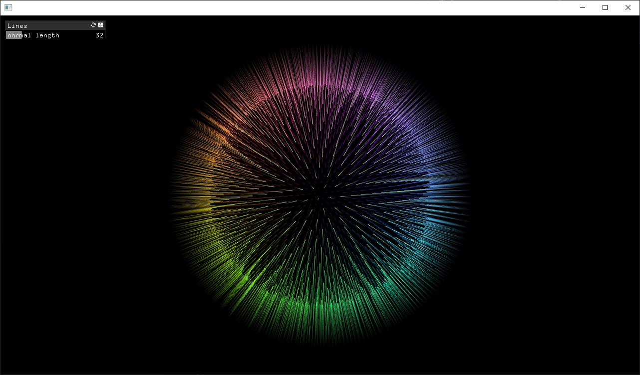
They can also convert the topology from the input to the output render. For example, we can write a geometry shader to draw lines representing a mesh’s vertex normals. This would take in a GL_POINTS topology and output GL_LINES.
When using a geometry shader, the vertex shader does not set a value in gl_Position. This is now set in the geometry shader. Any varyings the vertex unit generates will be accessible in the geometry unit.
|
|
The geometry program has special layout commands at the top that indicate the inputs and outputs.
layout (...) in;indicates the input geometry andlayout (...) out;indicates the output geometry.- Possible values for the input topology are
points,lines, ortriangles. - Possible values for the output topology are
points,line_strip, ortriangle_strip. - The output command also needs to include a
max_verticesvalue, which indicates the number of vertices that will be output when the geometry shader runs.
|
|
The varyings come into the geometry shader as arrays. The number of elements in the array depends on the input topology. points will produce just 1 element, lines will produce 2 elements, and triangles will produce 3 elements. Having access to all vertices that are part of the “face” can be useful in the calculations we make.
|
|
Vertices are output by setting the value of varyings, then calling EmitVertex(). This will push out the values as a vertex, for further processing in the fragment shader. We can also call EndPrimitive() after emitting vertices if we want to separate our faces. For example, if we are using the triangle_strip output topology but want to output separate triangles, we can call EndPrimitive() after every 3 calls to EmitVertex() to reset the strip.
The output varyings have to be set for each vertex. In our example, this means the built-in gl_Position and the custom vColor both need to be set.
|
|
The fragment shader remains unchanged. It just needs to output a vec4 varying for the pixel color.
|
|
We can also add an option to calculate and draw face normals, by changing the input geometry from points to triangles, and taking the average of the 3 vertex points that form a triangle to calculate the face normal.
|
|
|
|
Download the “Lines” project here.
Unity
Unity is a cross-platform tool used primarily for making games, but that can also be used for graphics applications and interactive installations. Unity has a graphical user interface for its scene graph which makes it easy to use, giving the programmer visual feedback as they build their applications.
Unity rendering works similarly to three.js. A mesh is added to the world and a material is applied to the mesh. The material can use a built-in shader or a custom shader to render the mesh.
Shaders in Unity are written in a language called ShaderLab. A ShaderLab file consists of many parts.
Shader is the top-level group that encapsulates all the other sections. The shader name is defined here.
|
|
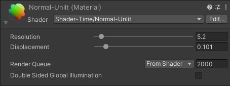
A Properties section at the top lists the uniforms used in the file. Using special syntax to define their type, default value, and range, these are automatically exposed in the GUI and can be edited on-the-fly.
|
|
A Subshader section has all the parameters and code for a shader.
- This includes properties like blending and culling, as well as the code for all the shader units (vertex, fragment, geometry, etc).
- Different shader passes can run in a subshader, each inside a
Passsection. By default all passes will run in order, but you can also call specific passes directly using advanced commands. - The code is written between
CGPROGRAMandENDCGcommands.
|
|
The shader code is written in Cg/HLSL. This is a different language than GLSL with its own syntax, but most of the concepts remain the same.
One difference you will notice is the data types.
vec2,vec3,vec4,mat4becomefloat2,float3,float4,float4x4.floatis sometimes replaced byhalf(a half resolutionfloat) orfixed(a fixed precision decimal number) for variables that do not require full precision values.
Attributes and varyings are organized into a struct. They also are tagged with semantics, which indicate their intended use. Semantics are used when referencing data. For example, we upload data to the POSITION and NORMAL slots in the mesh from the CPU, and we don’t need to know that the variables are called position and normal on the GPU (they could in fact be called anything). The SV_POSITION semantic in the vertex output represents the clip space position, equivalent to gl_Position in GLSL. For any custom data, we can use any of the TEXCOORD# semantics.
|
|
Vertex and fragment functions are part of the same code block.
#pragma vertex XXXand#pragma fragment XXXcommands are used to define which functions are used for which unit. (TheXXXis the name of the function.)- The functions take in a struct with the attributes or varyings as their argument, and have the output as their
returnvalue.
|
|
Geometry Shaders
Geometry shaders can be built in a similar fashion.
A struct is defined for varyings out of the geometry unit. This will be the new argument for the fragment function.
|
|
A function is defined for the geometry shader.
- A
#pragma geometry XXXcommand is added to define the geometry function. - The function’s first argument is the input geometry. It is tagged with a topology like
triangleorpoint. - The function’s second argument is the output geometry. It is tagged with the
inoutmodifier and a Stream-Output class representing the topology, likeLineStreamorTriangleStream. - The output vertex count is defined in the
[maxvertexcount()]function keyword. - Vertices are emitted by calling
Append()on the Stream-Output object. This is equivalent toEmitVertex()in GLSL.
|
|
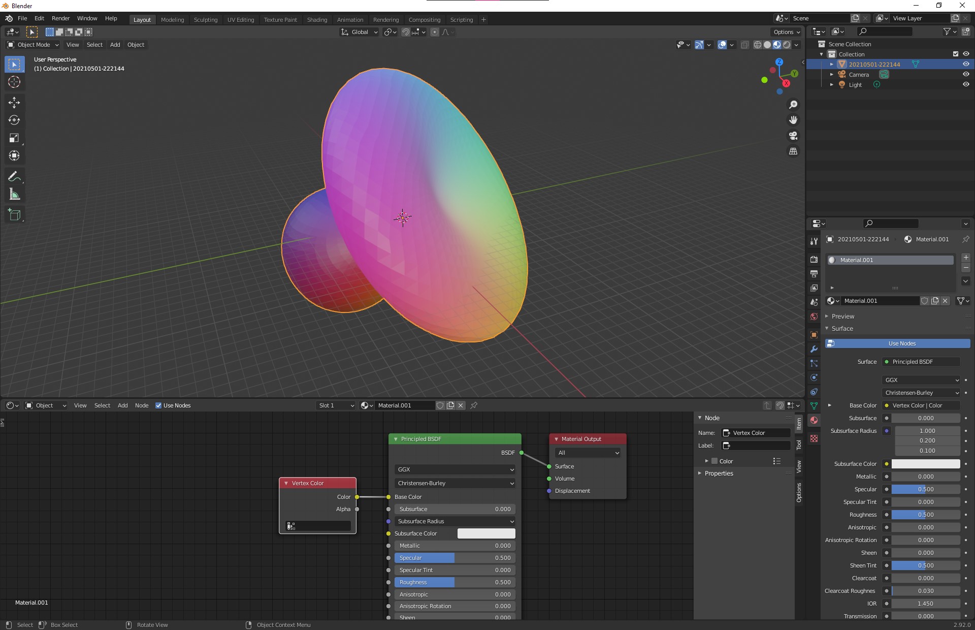
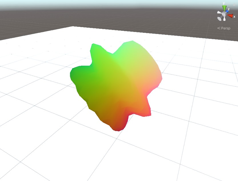
Surface Shaders
ShaderLab can also use something called the Unity Standard pipeline, where only a surface shader is required. Surface shaders are not actual shader units, they are special intermediate functions used to set fragment properties for Unity’s standard lighting function. This lighting function happens in a complex fragment shader which is hidden from us, as we do not need to worry about the details of its implementation. Writing surface shaders allows our materials to use Unity lights, shadows, reflections without having to code them ourselves.
The surface function provides an inout SurfaceOutputStandard struct as an argument. We just need to fill in the values we want to set on this object and let the rest of the pipeline take care of computing the final color.
We can optionally add a vertex displacement function as well, which will be run before the surface function.
These parameters as well as any options are all set in a single #pragma command.
|
|
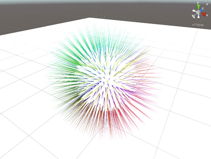
Compute Shaders
Compute shaders are GPGPU programs that run outside of the rendering pipeline. They do not render anything to the screen or to any offscreen buffers. These shaders offer the most freedom but this also comes at the price of complexity. There is no framework to follow, it is up to the programmer to set up the input data, the output data, the functions to execute, and even how the workload is split among the threads and thread groups on the GPU.
In Unity, the compute shader program is represented by the ComputeShader class and the data is managed inside a ComputeBuffer container. A standard Unity script is usually required to load the shader, build and upload the input data, and run the shader.
The data is just an array of numbers, usually float, which are usually organized into structs. It is a good idea to keep the stride a multiple of 4 floats for compatibility and performance on the GPU.
|
|
ComputeBuffer objects must be allocated with enough memory to hold all the data. Our example will load position and normal vertex attributes from a pre-existing mesh into a source buffer, and prepare a destination buffer for position and color output attributes. The program will generate lines (2 vertices) from points (1 vertex), so the destination buffer should hold twice as much data as the source buffer.
|
|
The compute shader will then be dispatched every frame, overwriting the previous data.
- A
ComputeShadercan hold many functions, or kernels. We need to tell the GPU which function to run by selecting the kernel with theComputeShader.FindKernel()function. - A
ComputeBufferis passed into the shader as a uniform using theComputeShader.SetBuffer()function. Note that this function also requires the kernel ID, as some uniforms like buffers and textures are tied to a kernel. - The shader is run by calling the
ComputeShader.Dispatch()function. This function takes the number of workgroups in 3 dimensions to split the workload into. The shader code will define how many threads run in each workgroup.
|
|
The shader code must define corresponding structs for the input and output buffers as the ones we created on the CPU, but using Cg syntax.
|
|
Uniform buffers are defined as StructuredBuffer for input data (read-only) and RWStructuredBuffer for output data (read-write).
|
|
- The kernel function is defined using a
#pragma kernelcommand. - The number of threads per group is defined in the
[numthreads(,,)]function keyword. - The thread dispatch ID is passed as a function argument. This value can be used to determine which index in the buffers correspond to this shader instance.
|
|
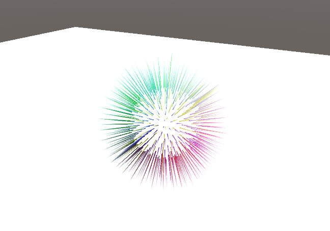
Back on the CPU, we can use the output buffer from our compute shader as an input to a standard rendering shader. As we do not have any meshes to render, only data, we call Graphics.DrawProcedural() with a count value, which tells the GPU how many times to execute the vertex shader.
|
|
We can pass the buffer into the rendering shader as a uniform, and define it with a corresponding struct in our ShaderLab code.
Since we do not have any input geometry, our vertex shader has no attributes to work with as input. We will therefore pass a variable with semantic SV_VertexID as an argument, which will just be a vertex index we can use to pull data from our buffer array.
|
|
Download the Unity project with all examples here.
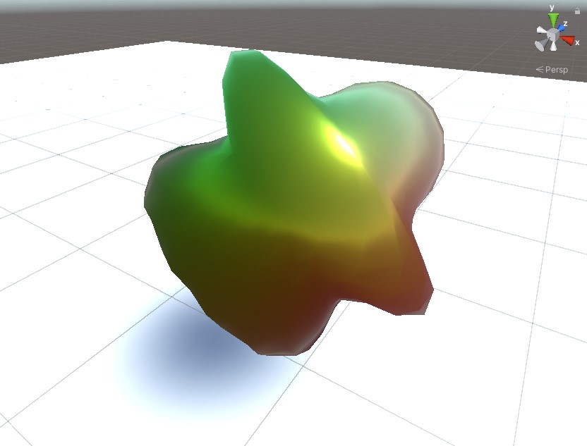
Shader Graphs
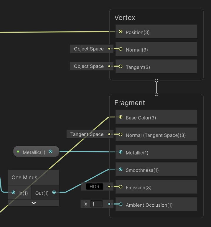
Over the last few years, Unity has been developing the next version of their graphics pipeline, the Universal Rendering Pipeline (URP). This scriptable pipeline features better quality graphics at better performance, and includes a graphical shader editor.
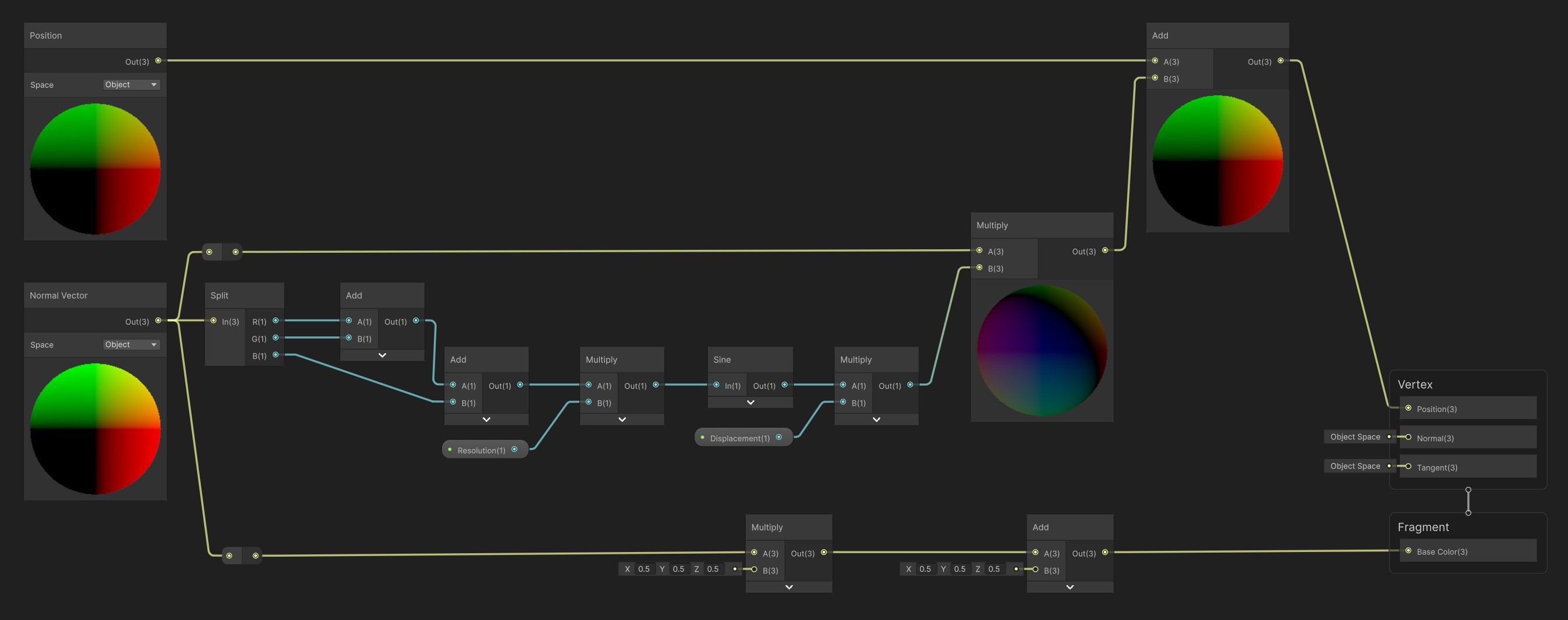
The Shader Graph is a node-based shader editor. Instead of writing code, you build networks of nodes that operate on input attributes and uniforms, and feed their results into output nodes for the vertex, fragment, and surface stages of the shader. Under the hood, these node networks get compiled to shader programs in GLSL, HLSL, etc. depending on the output platform.
Download the Unity URP project with all examples here.