three.js built-in geometries like SphereGeometry or BoxGeometry are very handy for basic shapes, but we will sometimes want to build our own geometries from scratch. We can do this by creating a BufferGeometry object, and adding our own data to it.
This is similar to using beginVertex(), vertex(), endVertex() in p5.js, but there are a few differences.
The data does not need to be re-added every frame (like in the p5.js draw() function). Once the BufferGeometry is added to a Mesh and the mesh is added to the scene, it will be drawn every time we re-render the scene. This is similar to how the rest of three.js works, once an object is added to the scene, it persists until it is explicitly removed.
|
|
To add our mesh attributes, we first create arrays to hold the data. These arrays should only hold components of the same data type (often float, but can also be int, short, etc.)
Multi-component attributes, for example position which has 3 components for XYZ, will have these listed in order one after the other. The array on its own has no way of delimiting which values belong to which vertex, it is just a list of numbers XYZXYZXYZXYZ...
|
|
The attribute is set in the geometry and the corresponding data passed to it using the BufferGeometry.setAttribute() function.
- The first parameter is the name of the attribute, which should match the name we use in the shader code.
- The second parameter is the array of data, wrapped in a
BufferAttribute.
The purpose of the BufferAttribute is two-fold:
- Since Javascript is untyped but graphics types are strictly enforced, the
BufferAttributeinforms the GPU how to interpret the array of data. We are mostly usingfloat, so we will mostly be using the correspondingFloat32BufferAttribute. (32 stands for the number of bits in eachfloat). - Since our array is just a list of numbers, we need to indicate which numbers belong to which vertex. By passing an item size, the
BufferAttributewill be able to split the array correctly. Note that this should match the data types in the GLSL code, so a type with 2 attributes will be avec2, with 3 attributes will be avec3, and so on.
Indices
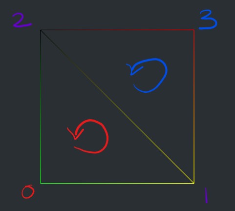
We notice in the example above that solid geometries are drawn using triangles (or gl.TRIANGLES), with every 3 points making up a face. This is why the fourth vertex is ignored and only one triangle is rendered. There is no way to set the topology to gl.TRIANGLE_STRIP or gl.TRIANGLE_FAN. (We can use the Points, Line, and LineSegments objects for points and lines, but will not look at this today.)
Using triangle strips and fans had the advantage of optimizing our data, as we did not need to duplicate vertices. However, they were not very straightforward to use, especially with more complex shapes.
Another optimization technique we can use is called indexed geometry. Indices are an additional type of data we provide to a geometry which gives it a “draw order” for the vertices. Like the name implies, it is a list (array) of index values for the vertex attribute arrays. Instead of drawing the vertices in the order they are in the array, they will be drawn in the order provided by the indices.
|
|
The index array can have repeat values so if our shape has shared vertices, we don’t need to duplicate the data, we just re-use the index.
The index array is set using the BufferGeometry.setIndex() function.
If we change the order of the indices or rotate the camera behind the quad, we will notice that it disappears. This is because three.js will only render front faces by default and will cull (or hide) back faces. This is standard in most graphics frameworks as a way to optimize rendering.
Faces are defined as front-facing or back-facing by their winding order. This is the direction, clockwise or counter-clockwise, that the vertex positions are ordered in space. Looking at our example above, we can tell that three.js considers counter-clockwise winding to be front-facing.
The winding order is unfortunately not standard amongst graphics libraries and should be tested when working in a new environment.
One way to avoid this is to tell the renderer to draw both front and back faces. In three.js, this can be achieved by setting the Material.side property to THREE.DoubleSide.
We can add more detail to our custom mesh by adding more vertices to cover the same surface area. We will do this using two loops, the first to populate the vertex attributes and the second to populate the index list.
|
|
We first create rows and columns of points. In this example, our ranges do not change: position is between [-2.0, 2.0], and uv is between [0.0, 1.0]. The change is in the distance between the points, which is dependent on the number of segments.
|
|
Next we build a list of indices to draw two triangles between each set of 4 points. For each iteration we look at the current point, the one immediately to the right of it, the one immediately above it, and the one immediately above-right of it. Because we are using nested loops for the width and the height, we can just add 1 to the index to get the next value.
Custom Attributes
Our examples so far have used the standard position and uv attributes, but this is not required. We are controlling every step of the pipeline at this point so we have the freedom to customize the geometry input as we please. We can name the attributes anything we want, and we can even add new attributes for any purpose. These are just extra per-vertex values we can then use in the shader.
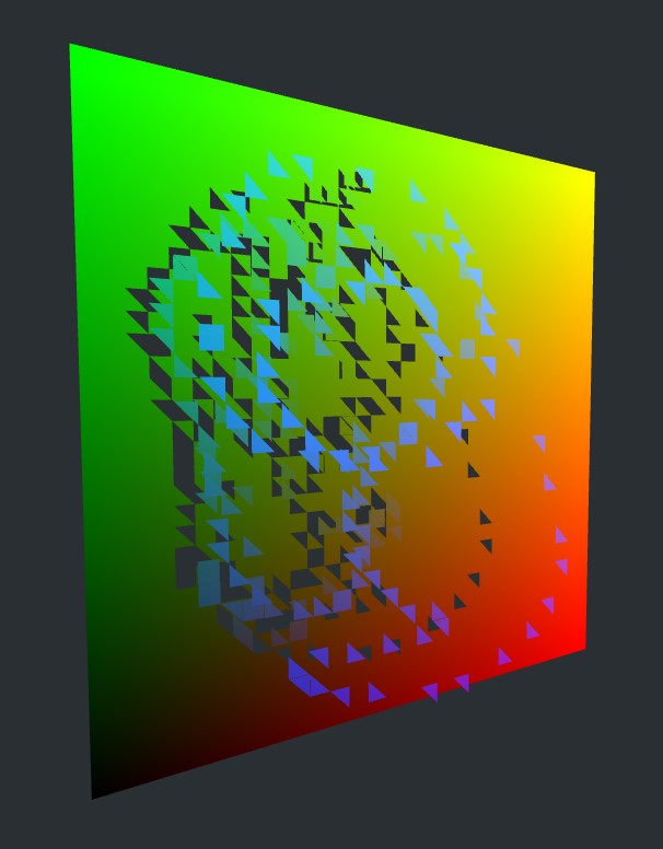
Let’s add an extent attribute and use it to push the vertex forward. The new attribute is added the same way: we first populate an array with data and then pass that data to our geometry with BufferGeometry.setAttribute(). The value can be used in the shader as long as we match the attribute name and type!
Raycasting
Attributes don’t need to be static, they can change over time. We can add mouse interactivity to our sketch and use the cursor to change the value of our extent.
Mapping the mouse position in our p5.js shaders was fairly simple, we just remapped the canvas bounds to our drawing rect bounds, but this only works when the drawing surface is flat and perpendicular to the camera. Imagine having to figure out which point on a spinning sphere is under the mouse. This is a situation where raycasting can be helpful.
As the name implies, raycasting consists of “casting a ray”, usually to find a point of intersection between the ray and a group of objects. Depending on the algorithms used, raycasting can return the nearest point that the ray touches, all the points that the ray goes through, or anything in between. Raycasting is powerful because it works in 3D. A ray can start at any position and go in any direction, it is not limited by a 2D canvas.
In our case, we want to cast a ray from the position of the mouse on the surface of the screen straight into our 3D world (i.e. following the camera’s z-axis). If any object is crossed by this ray, we will know it is under the mouse.
|
|
The mouse position must still be converted to clip space first. We will do the same operation we’ve done many times already: normalize the mouse coordinates by dividing them by the window width and height, then remapping the range from [0, 1] to [-1, 1]. The 2D screen and the 3D world have different y-directions, so we also need to flip the y coordinate. We store this value in a variable that is updated whenever the mouse moves.
|
|
Next we create a Raycaster object and set the ray using Raycaster.setFromCamera() when the mouse is clicked. We then call Raycaster.intersectObject() passing the mesh as a parameter to see if the ray and the plane collide at any point.
Raycaster.intersectObject returns something called an Intersection, which holds lots of useful data. We can get the exact position and uv value on the geometry where the ray hit, and we can also get the face (i.e. triangle) where the collision happened. The face has a, b, and c properties pointing to the vertex indices of the corresponding triangle.
|
|
We can use these indices to find the matching BufferAttribute data in the BufferGeometry.attributes object. We can modify the attribute values directly in the BufferAttribute.array object, and if we do we must flag there was a change by setting BufferAttribute.needsUpdate to true. This tells three.js to update the data on the GPU before rendering the next frame.
Rebuilding Geometries
Exercise
Our sketch currently has shared vertices between triangles. Update the BufferGeometry so that the triangles are completely independent, with no shared vertices. (You don’t need to use indexed geometry for this exercise.)
Existing geometries can also be used as source data for custom BufferGeometry. For example, we may want to build a sphere with no shared vertices. In this situation, we would not want to have to figure out how to lay out our positions, UVs, normals, faces, etc. from scratch. Instead, we can build a temporary SphereGeometry object and pull all the vertex attribute and index information from it. We can copy this information into a new BufferGeometry which we’ll use for a Mesh we add to the scene, but reconfigure it for our needs.
To build a sphere with no shared vertices, we can loop through the index array to add a new vertex for each index. This will duplicate any shared vertices, each with their own copy of the data.
This is pretty tedious work but luckily, we won’t need to do this manually again! We can use the BufferGeometry.toNonIndexed() function to generate a non-indexed version of any indexed geometry.
Pulling the position in the z-direction does not work for the sphere since it is not a flat shape (all faces are not facing the screen, like our quad). Instead, we will need to pull the position along the normal direction, perpendicular to the surface.
We will also remap the extent value using a sin() function, so that the triangle smoothly rises off and falls to the surface, instead of just popping up instantly.